Product Description
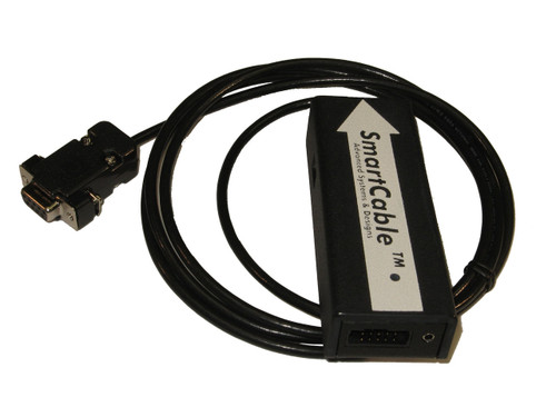
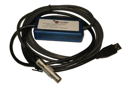
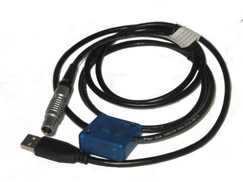
Mahr Federal Maxum III E1 Indicator SmartCable with Relay Output
Displays GREEN / RED Go or No-Go Signal
This SmartCable™ gage interface for the Mahr Federal Maxum III digital indicator with relay output is configured for use with Maxum III E1 (6-pin) digital indicators and will output built-in contact closure relays and/or optional RS-232 data. Based on DIP switch configuration / mode switch selection, this SmartCable™ gage interface displays GO (Green) / NO-GO (Red) LED indicators and has an audible NO-GO output.
NOTE: The Mahr Federal Maxum III digital indicator must be set to standard (Sto) mode. An optional RS-232 serial connection sends gage information to data acquisition systems such as communication and terminal emulation programs (i.e. HyperTerminal) or SPC data collection software programs. Call for pricing.
A detailed operation manual is included with each SmartCable™ gage interface including instructions on how to configure your Mahr Federal gage for the proper output format. Includes 300-10E power supply.
Output Cable Color Code:
Black: Relay1 Output #1 (Green LED)
Brown: Relay 1 Output #1
Yellow: Relay 2 Output #2 (Red LED)
Orange: Relay 2 Output #2
Red Wire: 9V Input power (9V DC, when power supply is not used)
Drain: GND
Optional RS232 Ouput: Blue Wire RS-232 TxD, White WireRS-232 RxD
DIP Switch Configuration:
-
DIP Switch # 1: Selects Output Mode. OFF selects normal “static” mode where readings are taken and outputs are updated only when the external foot switch is pressed or RS-232 host commands are received. ON selects “dynamic” mode where readings are constantly taken and all outputs are updated continuously.
-
DIP Switch #2: Selects Relay Mode. OFF selects mode #1 where relay #1 closes every time a reading is taken allowing a'parts count' or similar use, and relay #2 closes only when the part measured out of "spec" allowing GO/NO-GO indication or similar use (Note: relay #2 will close within the timing of relay #1). ON mode #2 selects where relay #1 closes only when a part measured out of "spec" on the upper limit and relay #2 closes only when a part measures out of "spec" on the lower limit.
-
DIP Switch #3: Selects GO/NO-GO LED light indication. ON selects go/no-go LED indication. Also selects beeper mode. OFF selects no beeper output. ON selects beeper output for no-go conditions
-
DIP Switch #4: Selects Relay Output Timing. OFF selects approximately 1 .5 sec relay closure timing, ON selects approximately. 150 msec relay closure timing.
Relay Specifications:
| Coil Volt. (VDC) | Coil Res. (. ) | Pickup/ Dropout (VDC@ 25o C) | Switch. Volt. (VDC) | Switch Current (Amps) | Carry Current (Amps) | Cont. Res. (. ) | Oper. / Rel. Time (msec) | Ins. Res. (. ) |
| 5 | 500 | 3.75/0.5 | 200 | 0.5 | 1.2 | 0.150 | 1.0/1.0 | 1010 |


